You are browsing as a guest. Sign up (or log in) to start making projects!

∇Calc

Hardware
  • 19 Devlogs
  • 24 Total hours
Open comments for this post

52m 1s logged

I kept routing. I made the port expander matrix (the one on the FPC in the center left), the header for the camera, and practically all the ESP pins :esp32-s3:
I’m still thinking about tidying it up a bit to reduce the number of traces going into the antenna area. There have to be traces coming there, it’s already acceptable as it is, but I will optimize…


That’s kind of it. :pcb:

0
0
2
Open comments for this post

1h 36m 7s logged

I was researching, looking at some more DOCS and just tidying up the last bits to start routing. I used Perplexity for some research and to cross-check data and see the trace widths for the NETs.
I put DRC rules, so it’s much easier to work, because when you activate routing on a NET it automatically sets that thickness and rules in the project.
I routed these more critical parts, power, data, a bit of the display part and stuff like that. Even with plenty of space, it already got a bit messy. This is my third board, so I’m still not that experienced with it.
But this is the way to go. Most likely I won’t have to go back and change components. I just need to finish routing, think about the case and its mechanics


What annoys me the most is having to return/exchange a component or it not being what I expect. In the case of marketplace sales, stores like Aliexpress

3
0
14
Open comments for this post

43m 42s logged

What I changed


At the top, there’s the 2x11 header for the ArduCAM module—you just need to plug it in. I also added a few more devices (actually kind of switched around their positions and values).
I hadn’t shown it before, but I imported this 3D model and linked it to the display device.
I did a general cleanup and a lot more research, tests, t hings like that.


I’m doing kinda okay. I kept waiting for the sellers to respond to me. But I didn’t get much, I could only get one reply per day. I would send messages there, but it was like 11hrs over there, outside their working hours. A lot of time for nothing… Also, that display manual/datasheet didn’t come with the dimensions of the display assembly, like the total height and the screen size I needed. I found it on a website, and it said 6mm, so I left that to do the 3D design to import the STEP as a 3D model. Another seller said they didn’t have the manufacturer’s data I needed for the camera to check the dimensions and the bus.


I wanted one that was 3.3V, and usually it’s the common 22 or 24 pins. But random ones from Aliexpress can easily change something in the pinout or order, which breaks everything. Here I’m kind of developing the project blindly. It has to be a really precise version, and that’s difficult… I think I’m going to go with the ArduCam module. It’s not small or as modular as others, but for my case it’s probably okay. (until now YES)

0
0
3
Open comments for this post

1h 41m 8s logged

As I said, I was going to send a message to the sellers, but I procrastinated, and by the time I sent it, it was already the weekend there. The sellers are Chinese, so their time zone is 11 hours ahead. Actually, it’s already Monday there now, so I think there’s no need to resend the message since mine is already in the queue (I hope…). Anyway, I messed around a bit more, organized the schematics a little better, added a few things, and thought about, more or less, how the items could/should be distributed on the PCB, so I did that with the images. So, this whole size isn’t totally necessary. It will help when routing, but there really aren’t any problems with that. What I might do is remove the part where the display goes since it will be securely framed in the future case.


They sent the link to the display manual

3
0
8
Open comments for this post

42m logged

organizing schematics


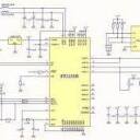
Here are the schematic pages I’m organizing:
01_SYSTEM_MCU, 02_POWER_USB, 03_KEYPAD_IO, 04_DISPLAY_STORAGE,
Actually, I’m still missing one more schematic image: 05_CAMERA_TBD.
It seems only four images are allowed per devlog.
That’s it—trying to follow a logical organization, with a left-to-right flow and the power sections included :|

0
0
4
Open comments for this post

1h 15m 18s logged

I added a few more components. The thing is, I’m preparing how I’m going to connect the keyboard/MCP of the keys to the circuit, and for that, I’m going to use an FPC for it and other LDO parts. Parts that deal with inductance/decoupling and protection of the circuit components.
I had to research and really look into things, and I’m already checking to find a module/version of the OV5640 with DVP FPC. I had to keep changing and reviewing the practical use of the components and kind of the electrical **‘needs’ **of the setup.

0
0
2
Open comments for this post

58m 4s logged

I switched the MCP MCP23017 to a QFN type. I realized that in the end, everything was most likely going to be pretty big. The final product thickness is around 15mm or more.


So now I’m studying and researching to change the components, organization, and then properly design the mechanics in CAD/case so everything stays stable. I didn’t really know the display dimensions. Some are kind of generic, with chip data/technical specifications giving a certain thickness, but most don’t have thickness. Looks like I’ll have to message the Aliexpress seller to get the exact data…

I feel way more lost than I should. It’s annoying because I had already thought a bit at the start and there wasn’t supposed to be so many reconstructions/pivots in the project.

0
0
5
Open comments for this post

1h 38m 4s logged

Well, what I kept working on was the case. I was thinking that the right way is to make three separate parts: the back part where a phone case fits (thinking in this case), the front part where there are holes for the display, keys/buttons, etc., and the sliding cover with the tracks. This one, when using a normal calculator, usually fits on the back of the body and when not, it fits on the front, storing and protecting the screen. In my ideas, I asked Gemini to generate these images to help me clarify my thoughts and development. It turned out good!


Another thing is that I noticed the display PCB module isn’t centered relative to the screen at all. Because of this, due to the width of the PCB and the case ending up close to the display module, it can’t be centered since there’s little free area for horizontal movement and the board would already touch the case walls. I made this 3D model to see roughly how it would look, and it looked weird. Not too much, but… The thing is, I usually do some stylizations, drawings, stuff like that.

It would be possible to put a solar panel there, yeah, but I’m not going to go back much to that part of the EDA and rethink the system, mechanics, and circuit logic.

0
0
2
Open comments for this post

2h 24m 12s logged

I was supposed to post yesterday but my uncles came over and I didn’t get back to it at night here


I’ve pretty much done the part that holds the PCB. The shell, I recessed inside it, and in the other picture you can see I made an Assembly to see how it was coming along and to have an idea of where the screw holes for the PCB are, and later what I should do on the case.
I haven’t done this yet, but you can see some Mate Connectors in the picture of the case alone (the light blue, slightly grayish part). I tried to make the holes, but the sketch planes and flat planes were on the top face and I couldn't make the holes. I spent some time trying that. I don’t know, but probably if I make a sketch on the bottom of the case I can make the holes.

That’s it, 3D for EasyEDA, I’ve already fixed it in Onshape and I’m doing well with the case part.

🫡🙂

0
0
1
Open comments for this post

51m 44s logged

I finished tweaking a few more things in the PCB schematic and getting it ready to export a STEP to use as a base in Onshape. Actually, I made the display way too big, standardized at 10 or 15mm, but it should be something like ~2.8mm. The thing is, when I was moving some items around, it ended up moving the Board Outline too, even though I didn’t select it… so I locked it to prevent that from happening, and I’ve already done the same in Onshape. Now I’ll start on the case and then come back to routing

0
0
1
Open comments for this post

1h 3m 1s logged

As I said, I didn’t see the dimensions of the full PCB for the 2.8 inch version, and because of that, I was going to need to change the board (since I don’t want to increase the size of the final product). So I went after the dimensions of the 2.4 inch version and made the rectangle just to represent the space it would take up in the PCB schematic.
A strange thing is that when I went to change the 3D model of the device, instead of changing it, it added another part to it. I had to overlap them so it wouldn’t look so weird there in EasyEDA.
Here is the image of parameters

0
0
3
Open comments for this post

1h 16m 8s logged

I was getting ready to start routing, but then I decided to take a quick look at the schematic again and check if the power supply and protection/best practices part of the circuit was all good. I consulted Perplexity and it suggested adding resistors and changing a capacitor on the EN pin of the ESP. I changed it from 100nF to 1uF and added a 10kΩ resistor along with it. I had already added resistors to the SDA and SCL pins and I don’t remember if I changed that..


I also looked up the data for the external components. The display and the battery. I wanted to make a 3D model to make it look better and to get an idea in the EasyEDA rendering. I searched for the display data on the site, on its manufacturer’s website but found nothing. So I googled it and the data came up on a site already known here and there it was fine, that must be it, I needed the thickness in this case ~15mm.


Ah, and I hadn’t noticed that the footprint I made for the display was only for the screen, not the complete module. Then I realized it’s going to be bigger than one of the PCB dimensions I had in mind… It’s supposed to be like that, I hadn’t noticed but in the image I attached with the green arrow it shows that it’s 50x86mm

0
0
1
Open comments for this post

1h 15m logged

Here I made some mistakes… I thought I had done the footprints, but after entering the 3D view/rendering of the PCB, I saw that there are only holes in the devices I made (these two in the attached images). I made some area that is seen as non-outline or something like that of the PCB. So I’ll have to fix that 😑

I also made an area on the board that will not have PCB material (FR-4) under the chip/module ESP antenna. This and the 15 mm keepout area around the antenna are to avoid interfering with Wi-Fi and Bluetooth connectivity.

0
0
3
Open comments for this post

1h 1m 8s logged

I kept working on the PCB schematic. After tidying it up a bit, I decided to make a device and footprint for the battery I’m going to use. It’s kind of standardized with dimensions of 10x34x50, A type with 2000mAh. That’s it, I made a rectangle of 84 by 165mm and put some holes 5mm away from the edges. I still need to figure out what type I’ll use, whether it’s countersunk or not. But either way, between 2.2 and 3mm.

0
0
3
Open comments for this post

1h 43m logged

I’m still working on the schematic… I was finishing organizing things and then messing around with the PCB design at the end. I’m going to call it PCB SCHEMATIC. Earlier I changed the display to a 2.8 inch one because I realized it was going to be too big, and the style I’m going for is kind of like this Casio ClassWiz

Here in the attached images are the drawings of the device and footprint.

0
0
1
Open comments for this post

1h 22m 4s logged

Here I tried to fix the NETs of the components and connections. I looked for the datasheets of the devices I’m using (it was easy since I just had to go back to LCSC with the Part Numbers, and on its page, the datasheet is already there). I downloaded them, some in English, others in Asian languages (I think if I remember correctly there was only Mandarin and Korean). I uploaded them to NotebookLM, and it gave me an overview of how things worked and pin data, that kind of stuff.

I saw that I had done some things wrong yesterday, so I had to fix the labels and that kind of stuff.

0
0
3
Open comments for this post

2h 5m 35s logged

I created another device—just to simulate the 3.5 LCD display I found on AliExpress. After doing some research and looking at other options, I decided against using Seeed’s S3 Sense. It comes with an OV2640 camera, but I’m going to use an external OV5640 module instead—a 5MP one I bought along with the other two.

I did some research, checked out components and versions in the LCSC library, verified a few things with Perplexity, and added the items to the schematic. It’s still pretty messy, but I’ll clean it up, organize it, and get the NET’s sorted out later.

0
0
3
Open comments for this post

46m 2s logged

Well, I started this project here… the idea I had was to make a node that is a ‘calculator’ from scratch. I’m not exactly sure if I’ll include multiple buttons or common functions in it, because the difference with this one is having access to the AI API, and I’m also thinking about adding Wolfram Alpha. It’s going to have a camera to take a picture of the equation, send it to the API, and it returns an image of the solution. It connects to Wi-Fi and sends the data to a server where it’s processed, formatted in LaTeX, and then returns the image.

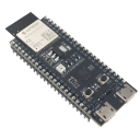
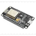
So I started by putting the components in the EasyEDA schematic and created a simple device that was supposed to be the Seeed Xiao ESP32 S3

0
0
3

Delete project?

Are you sure you want to permanently delete this project? This action cannot be undone.

All devlogs, followers, and associated data will be removed.

Followers

Loading…