Ship
Pending review


First, I would like to apologize for the ragebait that is the previous devlog.

But anyway, in this devlog I refined the GUI a lot, did debugging and got ready to ship!
The previous version of the UI was kind of scuffed and was missing a lot of features. The new UI fixes most of these and adds more stuff:
 Now you can actually add devices and see their specific UIs within the UI! this took way too long to implement


 Now the UI doesn’t update every clock cycle (Quite a lot at 500,000 hertz
 )



So far the entire interface for the project is just a terminal with some print statements and sometimes a display window  so I finally made some frontend GUI!


The idea for this was a full window showing everything that the processor is currently doing, including the various subsystems and components of the emulated CPU, the registers, pins, settings and other stuff 
It also has a cool section for programming it, with which you can write code or import programs, assemble them, load them into the CPU and run them with only a few clicks. 
With the new GUI you also can modify everything in the CPU however you wish  so you can change register values (even the read only ones ), fire pins, change processor settings and other execution stuff, and also see and interact with the GUIs for devices! (gui inside gui
 )
believe it or not, netbeans, out of all IDEs, has an  amazing
 form editor, which is basically a UI designing thing for java, and that’s what I used to make the UI for this.
All you have to do is drag and drop stuff into the canvas and try not to crash out over its idiotic paranoid auto scale system, and it automagically generates all the layout code for you! if only it magically made all the UI work too 
See the design lapse here: https://lapse.hackclub.com/timelapse/j9cZMZqsB7Ia
uhh so the default GUI looks horrendous because it uses Java’s built in Swing UI elements and designs, which is fine, but it makes it look like its from 2009  BUT i can change it’s look using a different “Look and Feel”, which is basically defines how UI elements should look. and feel.

For this project I decided to use the FlatLaf look and feel which made it look a lot more modern and also made it a bit nicer to use.
I didn’t use maven for this because I have trauma from when i used maven a long time ago and it uninstalled my entire project with no backups also java yum



this is the hard part
Okay now the UI looks nice and all but it does nothing and is useless because it’s not linked to the backend
Anyway I wrote a lot of messy code and linked up the processor backend and the assembler to the UI, and also wired up all 28 registers, 8 pins and a bunch of settings, initialization and assembling stuff to the backend.
The thing is, I need to update the backend from the frontend and the frontend from the backend, and if that happens incorrectly or in the wrong order, which it does a lot, wrong or invalid information can be fed to the backend (and the frontend) which ruins the entire execution flow. 
There were so many problems with the UI and backend not matching up, like:



and a lot of other bugs
After consuming  all of the remaining bugs and testing it a lot, I finally had a UI that worked and synced with the backend properly… mostly.
This is a prototype and I still need to change a lot of stuff, but here’s a screenshot of the finished UI while executing the previous 3D renderer thing


I finally got the 3D renderer to work It took SO long (18+ hours in total? ) but it’s so cool and really shows the capabilities of this tiny CPU
It took so long to make because I had to write everything in assembly with 🚫 no functions, 🚫 no control structures and 🚫no variables
Obviously trying to program this CPU with such a tiny ISA and a stupid assembler is borderline impossible - you have to manually deal with register/pin addresses and memory addresses for jumps, so adding a single line changes everything after it and breaks your jumps. 
That’s why I added a few features to the assembler to make my life easier, namely address markers and constants.
)Additionally, I also introduced a dynamic constants thing in the assembler, which basically just reserves memory addresses and stuff for constants on it’s own, so now I don’t even need to think about those addresses.
I added a new ALU (Arithmetic & Logic Unit) function in the CPU for comparisons between two numbers.
The new COMP ALU operation compares the two values in ALU_A and ALU_B and sets the output to:
Trying to make a 3D renderer without these functions is impossible
Ok, now onto how the renderer actually works.
The renderer is just one big program (1300+ lines of assembly) that does a bunch of stuff to try and render a spinning cube on the display. Basically all it does is:
 Initialize the cube vertices Make the edge table for the lines of the cube Rotate all the points of the cube by a set amount every frame using a lot of scary math
 Draw all the lines of the cube and refresh the display
 Repeat from step 3
Here’s a very simplified explanation of the entire program:
The initial positions of the points is hardcoded into the code, and there’s also a getVertex function to get the X, Y and Z coordinates for a specific vertex number.
To rotate the points, you need to do some matrix multiplication  on each of the points, with a rotation matrix thingy and magically rotation happens.
I don’t actually know what sin/cos is, they didn’t teach us in school yet as far as I know it’s something to do with the angles of a right angle triangle or whatever who cares
To find the rotated points, it takes each of the coordinates and multiplies X by cos theta + Z * sin theta, and multiplies Z by -X * sin theta + Z * cos theta, where theta is the value it is being rotated by. Sin and Cos values for values 0-90 degrees are hardcoded into the program because it’s very hard to calculate
Then the program takes those rotated points, and projects them into 2D points. Those equations are much easier:
Projected X = (X * FocalLength)/(Z+FocalLength)
and similarly,
Projected Y = (Y * FocalLength)/(Z+FocalLength)
Then it draws the lines between the points using a hardcoded edge table and bresenham’s line drawing algorithm.
It then releases the pixel buffer and gets ready to draw another frame!
And after a lot of debugging, it’s finally finished!
(The video is at 500 kilohertz btw  )

So I was working on a 3D rendering program
Writing a whole 3D render in assembly was slightly overambitious I think. It took thousands of lines of code and hundreds of memory allocations, functions and random stuff.
It is supposed to be able to do rotation, projection, and wireframe drawing, and I tried making it draw a simple cube.
As of right now it doesn’t work. Debugging DTA assembly is hard especially when you have 1400 lines of it. (i thought of splitting it up into several files, but the way that it’s assembled and stuff makes it difficult, I still do have many files but I merge them all before assembling)
There’s some problems with the math and conditional stuff and if i try to run the whole renderer the screen just shows one pixel at coordinates (0, 0) flickering.
But I was able to program a functional line drawing algorithm based on generalized Bresenham’s line drawing algorithm! (see picture) It basically works by taking two start and end coordinates, and adjusting the x towards the end coordinate, while measuring the error of the y-coordinate from the ideal line and adjusting for it. idk im bad at explaining things.
I’ll probably write more about this in detail once I get the 3D renderer fully working.


I made an assembler now so that I don’t have to write the raw ROM bytes to write programs!
You can now just write code in assembly and it will magically generate the perfect ROM values!
It can do a lot of cool stuff like:
set pc, bruh to jump to the instruction you labelled “bruh” for some reason

The label thing is especially useful because I don’t need to rewrite a bunch of stuff just to add some code, and I don’t need to think about instruction addresses at all now because it all happens automagically with the assembler!
I also created a bunch of new programs using this assembler, that use some of the new device stuff as well. speaking of device stuff,
I changed the architecture of the DSC a lot and now there are separate pulse pins that you can use to talk to the device. This makes working with devices a little bit easier and uses lesser code as well!
With the new architecture I made some new devices as well, like:
 A colour GPU Now you can draw pixels to the screen that aren’t black and white! It actually includes all 0-255 values for red, green and blue, like all modern gpus and displays have
 Work in progress text renderer terminal thing
 Power Management Thing™ so that programs can view and adjust the processors clock speed

I also made one of those cool GPU test gradient things for the new GPU  It does a lot of math and loop stuff to figure out which color should be at which position. I wrote it in like 80 lines of assembly using the new assembler and it takes about 16 seconds to finish at 10 kilohertz.
This is the picture of the output:

I worked on the backend of the emulator a lot. I coded the remaining parts of all of the components, then I made a clock and finally put everything together to make the working emulator.
The processor can now execute all three DTA instructions properly: COPY, SET, and PULSE The instruction decoder reads the instruction words, figures out what operation needs to happen, and the processor performs it through the appropriate registers and pins.
There were also a bunch of weird bugs like components not being able to update their own read-only registers and memory size limits
A processor isn’t very useful without any output devices so I made a GPU device to output pictures.
It has a 64x64 pixel screen to which the processor can write pixels to. It has only black and white pixels because… i was lazy ig 
I then tried running some programs on it!
Like one that continuously tries to write to read-only registers and throws infinite errors! ok that one was for testing
I tried making a program that actually uses the screen, and I thought of just drawing a checkerboard pattern on the screen.
Unfortunately I was too ambitious and it didn’t work. at all.
So i tried just drawing one pixel to the screen and WOW IT WORKED! no it didnt it still did nothing
I did a bunch of backend debugging stuff which is really boring and complicated and I had to move the device register update code in the DSC to its own pin and trigger method and akcgcrwqajhxte tldr a bunch of confusing stuff 
Finally i got the pixels to work! There was now one white pixel on the screen! exciting!
I had to do a lot more debugging for the checkerboard thing to work. I didn’t make an assembler as of now, so I had to write all the machine code myself (Literally writing with numbers)
And catching bugs was impossible because again, you’re looking at a bunch of numbers. Anything as simple as adding a line of code was a pain because it shifts the memory addresses of all the lines of code after that, which messes with jump conditions and stuff.
Despite all that IT WORKED it does run quite slow because its more than 30 instructions for each iteration of the loop, it takes a few seconds for it to finish the image at a clock speed of 10 kilohertz.
This is basically how the program works:
And then start running an infinite loop in which all this happens:
PIXEL instruction, X coordinate, Y coordinate and pixel colour to the GPU via the DSC.All that generates this cool checkerboard pattern on the screen.
(This is 44 lines of assembly )
Anyway look at this picture:

I’m making an emulator for a processor!
It’s supposed to be a very simple minimal instruction set computer, with only 3 instructions.
I mostly worked on the ISA in these hours and also did a bit of backend work for the emulator.
The instruction set for the processor has only 3 instructions:
The entire processor can be controlled just by changing the values in registers and pulsing stuff.
Copy copies the value of one register to another
Set directly sets the value of a register to something 
Pulse pulses a pin 
(This is also why it’s called DTA - Data Transfer Architecture)
With these simple instructions, you can manipulate registers and therefore control various parts of the processor!
Designing the processor ISA was very hard because there are a bunch of problems that arise from having only three instructions.
For example, this is how you would write a program to add two numbers from the memory and save it back to the memory.:
SET READADDR 1
COPY READOUT, ALU_A
SET READADDR 2
COPY READOUT, ALU_B
SET ALU_OP, ADD
SET WRITEADDR 3
COPY ALU_OUT, WRITEVAL
PULSE WRITE
This code first sets the read address to 1, causing the register bank’s read output to provide the value stored at address 1.
That value is then copied into ALU_A.
The read address is then set to 2, and the value at that address is copied into ALU_B.
ALU_OP is set to ADD.
Finally, the write address is set to 3. The ALU output is copied into WRITEVAL, and the write operation is pulsed, storing the result at address 3 in the register bank.
So basically, at a high level, it reads 2 values from the memory, copies them to the ALU input values, sets the ALU operation to addition, then saves the output back into the memory.
The memory reading and ALU output is combinational, ie it works continuously, and does not need a pulse for it to work. Meanwhile writing stuff to the memory can’t just be on forever, that would create problems. So we need to pulse it when it’s ready to write. You can think of pulses like triggering something
Hopefully you’re understanding 
The parts of the CPU are:


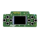
(this took way too long 🤦 )
That’s about it for the ISA. I also started working on the backend of the actual emulator by implementing all of these components individually in Java  (java peak )
A picture of all the registers and pins:


The main thing that I did in these 7 hours was making a graphical interface for the app.
I first designed the UI in the Netbeans Form Editor because it’s really easy to make it in there, then I exported all the code generated by that and then spent a lot of time wiring everything up and making the GUI stuff actually do something.
It has a bunch of new features and settings like:



which took very long to implement because it needed a lot of backend stuff
I also briefly overwrote a bunch of code and accidentally deleted the source folder but I managed to retrieve everything from the recycle bin
I then made another GUI for the initialization screen - where you choose the calibration method (manual or reported) in a similar way.
Did a lot of backend work as well, like changing how the image system calibrates stuff.
Also I made a nice readme and I’m going to ship soon! 

I added a file selection screen to choose which image to view.
There is also a nice grid background now which took way too long
woa you can put emojis now?
I also made a bunch of other small QoL improvements too, and this is how it looks now!
(not much of a visual difference compared to before )

I implemented another system where you can import an image, then draw a line and say how long that line is. Then the whole image stuff will be scaled proportional to that and then you can measure it and stuff!
I also added a bunch of other small things like improving the scale library backend, adding camera controls, etc.
It’s kind of barebones rn and this took way too long anyway, I’m going to add some menus/interfaces to tie everything together and some other QoL next ig.
Here’s a picture of a maze where I selected the big horizontal line and defined it as 170mm, and there’s some measurements on it.


I’m making a virtual scale! When modelling or designing stuff, it’s very easy to lose a sense of how big a measurement actually is. I constantly find myself grabbing a ruler just to visualize a distance. So I’m making a little virtual ruler that displays real-world measurements directly on your screen. It uses your screen’s dots-per-inch count (basically how many pixels are in an inch of the screen) to show accurate distances.
Today, I worked on the actual scale library/backend of the app and worked on the scale calibration, unit conversion and scale systems.